SYSTEMS DESCRIPTION
6.1 POWERPLANT & POWER SYSTEM
6.1.1 Engine
An AeroSport Power 0-320-b1A, Serial No. 0234, powers N91031D. The 0-320-D1A is a direct-drive, four-cylinder, horizontally opposed, normally aspirated, carbureted, air cooled engine. This engine is the Lycoming 0-320-01A, re-built and zero-timed by AeroSport Power in Kamloops, B.C., Canada.
The engine has the following specifications:
Rated maximum continuous power: 160 h.p. at 2700 RPM at standard sea level
- Displacement: Bore = 5.125 inches; stroke = 3.875 inches. Piston displacement of 319.8 cubic inches.
- Compression ratio of 8.5:1
- Spark Plug Firing Order: 1-3-4-2
- Weight: 285 pounds
- Oil Sump Capacity: 8 quarts (2 quarts minimum)
- Magneto Drive: 1.000:1, clockwise
- Carburetor: Marvel Schebler MA4SPA
- Ignition: LASAR Controller model LC-1011-01 (s/n 9920701); LASAR Magnetos #4771 (s/n 99051481; L), #4770 (s/n 98030487; R)
- Starter: B&C model BCS206-149 (s/n 23650811), manufactured 8/2011
- Alternator: Denso model 18504-6220; rated at 40 Amps
- Fuel: Grade: 100LL aviation fuel
- Fuel Pump: Mechanical diaphragm engine pump: Facet 40105 boost pump (from left tank)
- Oil: MIL-L-60828 or Ashless Dispersant SAE
- Oil Level Gauge: Manual dip-stick on aft right side
- Oil Consumption: 0.006 lb/BHP-hr (maximum)
- Oil Filter: Airwolf Model AFC-K001 Full-Flow installed on upper right side of firewall.
- Champion CH48019-1 or
- Tempest 48019 - Oil Cooler: Niagara Development & Mfg Co. (NOM) Model 20002A (s/N F99-3637-19): installed on lower left side of firewall.
- Oil Pressure Measurement: Westach mounted on the accessory case at the upper right-side of the engine
- EGT Measurement: Four K-type thermocouples, one installed in each exhaust pipe header
- CHT Measurement: Four 3-type thermocouples with bayonet mountings, one mounted in each cylinder head.
6.1.2 Propeller and Governor
N9103D is equipped with a two-blade Hartzell Model HC-M2YR‑2C LEUF constant-speed propeller, 73 inches in diameter. The propeller hub was designed for a Lycoming 0-360; steel bushings were fabricated and installed in the hub to accommodate the 7/16" mounting bolts for the 0-320.
The propeller governor is a Woodward Model 8210345, mounted on the accessory case, approximately mid-engine. The governor controls the pitch of the propeller by means of oil pressure. When the oil pressure is reduced, the propeller seeks a reduced pitch; that is, a higher RPM. The propeller oil line runs from the governor to the forward upper right side of the engine.
6.1.3 Fuel System
N9103D has four fuel tanks: two main tanks and two auxiliary tanks, one of each in each wing. The total fuel capacity is 50.6 gallons, with 45.1 usable gallons. The main tanks are located in the inner bay of each wing and have a total fuel capacity of 30.6 gallons, with 27.6 gallons usable. (15.3 gallons each, 13.8 gallons usable.) The auxiliary tanks are located in the outer bay of each wing and have a total fuel capacity of 20 gallons, with 17.5 gallons usable. (10 gallons each, 8.7 gallons usable).
Figure 6.0 shows an illustration of the fuel system. The auxiliary tanks feed directly to the main tanks by means of two independently operated Facet Model 40171 fuel transfer pumps, one in each wing. The pumps are located near the outboard inlets to the main tank and are accessible through an inspection hole. The transfer pump(s) are controlled by means of a Pillar Point Avionics Model XFR-J Fuel Pump Controller located in the cockpit.
The GlaStar's fuel system is primarily gravity-fed, with a boost pump in the left tank fuel line for starting, take-off, landing, and emergencies. An engine-driven fuel pump is also installed. The boost pump is located beneath the left pilot's seat and is controlled from a switch on the main switch panel in the cockpit.
Two header tanks ("saddle tanks") are located on the upper left and upper right vertical cage structures and provide a total of approximately 1/2 gallon of fuel reserve fuel.
The fuel from each header tank flows downward and forward to an Andair Left-Right-Both-Off fuel selector valve. A single fuel line runs forward from the fuel selector valve to a Steve's Aircraft SA-3 gascolator located on the lower right side of the engine firewall. From the gascolator, the fuel line runs to a mechanical fuel pump on the engine which supplies fuel pressure to the carburetor. A fuel flow sensor is installed just forward of the fuel selector valve and a fuel pressure sensor is installed in the line between the mechanical pump and the carburetor.
There are seven (7) sump drains in the fuel system: one on the bottom of each tank, located near the tank outlet; one belly drain at the lowest point of each main tank fuel line, located underneath the fuselage; and a gascolator drain.
The main fuel tanks vent through the auxiliary tanks. Each main tank vent line runs to a fitting on the upper outboard portion of the auxiliary tank. Each auxiliary tank is vented to the wingtip.
The fuel caps are of the locking, flush-mounted style. The fuel caps are opened by lifting the handle and rotating it 1-turn counter-clockwise. The caps are closed by rotating the handle 1-turn clockwise.
6.1.4 Oil System
The engine oil system uses a mechanical oil pump with a wet sump on the bottom of the engine. The oil is cooled by a Niagara Model 20002A oil cooler, located on the left side of the firewall. A SCAT tube from a NACA scoop on the left side of the engine cowling provides oil cooling air.
The oil capacity is eight (8) quarts. The recommended oil type and viscosity is shown below:
- 60W or 15W-50 or 20W-50 (above 80°F)
- 40W (30°F to 90°F)
- 30W or 20W-30 (below 10°F)
The oil dipstick and oil filler neck is located on the right side of the engine and is accessible through the oil check door. Refer to the Lycoming Operator's Manual for service intervals.
6.2 LANDING GEAR
All three gear legs on N9103D are of the Wittman-type tapered-rod design. The legs are made from heat-treated steel.
5.00 x 5 wheels and brakes are used on the main gear. The main-gear wheel pants were designed to accommodate the Michelin Air 5.00 x 5 tire, part #070-310-0. Use of a different brand of 5.00 x 5 tire may result in the main gear wheel pants not fitting the tires. A 5.00 x 5 wheel, fitted with an 11 x 4.00-5 tire, is used on the nose gear. Air pressure in the tires should be maintained at 40 psi.
Toe-in on the main gear is 1/32" measured at the end of the axle, or about 1/3°.
6.2.1 Brakes
Grove hydraulic brakes and Matco master cylinders are used, with toe pressure on the tops of the rudder pedals causing brake action. Dual brakes are provided, thus allowing either the pilot of co-pilot to operate the brakes. The brake fluid reservoir is mounted to the aft side of the firewall, above the co-pilot's rudder pedals. To prevent damage to the seals in the brake system, use only MIL-5606 type brake fluid.
A parking brake valve is provided in the brake line plumbing. The parking brake valve is located on the bottom of the fuselage centerline, beneath the center console.
6.3 Cowl Flaps
A ground-adjustable cowl flap is provided to maintain optimum engine operating temperatures.
6.4 Cockpit
The GlaStar provides side-by-side seating for two occupants, comfortable for persons up to 6 ft. 7 in tall and weighting up to 250 lb. The cabin width is approximately 44 inches wide.
The seats adjust by sliding the seat-back forward and aft to accommodate the leg lengths of the occupants. Adjustment is made by lifting the seat back-locking pins free of the detents in the seat rail track, moving the seat back to the desired position, and then re-inserting the locking pins into the holes in the slide mechanism.
The GlaStar has two cabin doors; each door is secured by a four-point latch system actuated by a single handle. The doors open fully forward. In N9103D, each door is key-lockable from the outside, using the ignition key.
The doors can be cracked open for ventilation during ground operations, but should be secured before flight. Because of the full-opening feature, the doors should also be secured when operating in gusty winds or when taxiing through the prop wash of another airplane.
Baggage is stored directly behind the seats and should be securely anchored down before and during flight. A locking baggage door is provided on the left side of the fuselage, just behind the pilot's door. Larger baggage can be loaded through the cabin doors by folding the seat backs forward. Tie-downs are provided to secure baggage items.
The baggage area has a maximum capacity of 245 lb. and is divided into two zones. The dividing line between the forward and aft baggage zones is located 25 inches forward of the baggage compartment bulkhead. Baggage loading requires weight-and-balance considerations in these zones. See Section 5.1.2 for details.
WARNING
DO NOT PLACE ANY SMALL LOOSE ARTICLES IN THE BAGGAGE COMPARTMENT. ALL BAGGAGE MUST BE STOWED IN CONTAINERS SUCH AS PACKS, SUITCASES OR BAGS. A SMALL ARTICLE COULD BECOME MISPLACED AND BIND UP THE CONTROL LINKAGE, CAUSING LOSS OF CONTROL OF THE AIRCRAFT.
6.5 HEATING AND VENTILATION
6.5.1 Heating
Cabin heat is provided by a heat exchanger (a "heat muff") mounted to the right-side exhaust pipe which is ducted to a heat valve located mid-line on the forward side of the firewall, and just above the nose-gear arm. Cabin heat is controlled by means of a push-pull cable located beneath the extreme right side of the instrument panel. Pulling the cable out increases the cabin heat; pushing the cable in decreases the cabin heat.
Windshield defrost is provided by avionics waste heat through a diverter box in the glare shield.
6.5.2 Ventilation
Cabin ventilation is provided by means of NACA-style fresh air inlets in the side of the fuselage. Each NACA-style duct is connected to an "eye-ball" ventilator valve. One valve is provided for each occupant. The vent valves are located on the lower kick panel, just beneath the instrument panel. To increases the ventilation, turn the top of the valve counterclockwise; to decrease the ventilation, turn the valve clockwise.
6.6 WING-FOLD SYSTEM
N9103D's wings can be folded and the horizontal stabilizer and elevator can be removed to permit the aircraft to be trailered or stored. Wing-fold supports struts are attached to the wings when folded. These struts help "unload" the spar pins, making them easier to remove, as well as holding the wing in the proper alignment so the spar lines up with the cage when the wing is folded back into the flight position. A second pair of struts is also provided to connect the wing rear spar and the vertical fin spar to hold the wings in their fully folded position.
To fold the wings, install the leading edge supports, remove the forward spar pin keeper and pin, rotate wing aft, secure with wing rear spar-vertical stabilizer struts.
Note: The two clevis strut eyebolts on the trailing edge of each wing have not been installed. See Wing folding for details.
See Section 7-4 for a complete description of wing-fold and stabilizer removal procedures. Two people are recommended for this task.
6.7 CONTROL SYSTEM
The primary controls on the GlaStar are of a conventional 3-axis cable-operated design using dual stick controls for pitch and roll and dual rudder pedals for yaw. Positive travel stops are provided for all primary controls.
Flaps are of the Fowler-type, actuated by a lever mounted between the seats. A thumb-operated button releases a
spring-loaded locking pin from a detent in a ratchet plate, allowing the lever to be moved to the desired position. The ratchet plate has three positions: from 0° to 40°.
The elevator, aileron and flap control interconnections are by cables to bellcranks, with a pushrod connecting each bellcrank to its control surface. The rudder is controlled by cables directly to the rudder actuator yoke. The aileron and flap control cables are routed in such a way that they do not need to be disconnected when the wings are folded.
The GlaStar elevator trim system uses a large trim tab in the elevator. The trim tab is adjusted by means of an electric servo mounted in the elevator. Trim control is accomplished using a trim control switch ("coolie hat") mounted on both control sticks that causes operation of the trim servo. An aileron trim tab (on the right wing) is similarly controlled by the coolie-hat switch mounted on the control sticks.
N9103D is equipped with a 2-axis Safety-Trim electronic servo speed-control system. The system replaced the original speed controller and relay module, resolving problems with intermittent operation. This installation provides reliable automatic high and low speed trim actuation. See Trim-Servo Controller for details.
Benefits
- Electronic-servo controller with speed control run-away protection
- Time-limited operation prevents trim servo run-away conditions
- Servo travel limited to 3 seconds per trim switch actuation
- Reverse-function switch allows pilot to recover from a stuck or failed trim switch
- Eliminated earlier relay decks and speed controller
- Simplified wiring, with no extra parts needed for pilot and co-pilot trim switches
- Designed for N9103D’s installed Ray Allen electric elevator and aileron trim servos
- Short circuit proof, reverse polarity protected
- 2-axis model provides automatic high and low speed elevator and aileron trim actuation
6.8 ELECTRICAL SYSTEM
N9103D has a 12V negative ground electrical system (see below). The electrical system was originally comprised of an Odyssey PC680 main battery and a smaller UltraStart Red back-up battery. To alleviate cold weather engine starting difficulties, both batteries were replaced with a heavy duty Odyssey ER30 battery. Wiring for the UltraStart Red was left unmodified, and thus may be reused in the future. See ER battery for details.

Basic layout of N9103D’s electrical system
Other components of the electrical system include a starter motor, 40-amp alternator, and numerous electrical and avionics items. All electrical and avionics equipment are grounded at a single point located on the aft side of the firewall, on the centerline just underneath the glare shield.
Power is distributed by means of a Control Vision EXP Bus II (see below). This bus controller also provides circuit protection to the attached electrical and avionics equipment by means of “poly fuses”—solid state circuit breakers that reset after the power to an affected circuit is completely removed. All circuits except for the pitot heat and the auxiliary power connector are protected by the poly fuses installed in the bus controller. Pitot heat and auxiliary power are protected with fuses. Power is switched to most of the electrical and avionics equipment using the switches on the instrument panel.

N9103D’s EXP Bus 2 schematic
The single Odyssey ER30 battery is located aft of the baggage area bulkhead (Bulkhead A); it is accessible by removing the bulkhead fasteners. The EXP Bus II is located just forward of the instrument panel, close to the fuselage on the extreme left side of the aircraft under the windshield. The starter and alternator are belt-driven and located on the forward, left and right sides (respectively) of the engine.
Two Master switches are installed in N9103D. "Master #1" provides the main battery power (from the Odyssey ER30 battery) to the bus, all bus circuits, and to the starter contactor. Master #2 is inactive because there is no back-up battery connected to its circuit. However, if a backup battery were installed, “Master #2” would switch the back-up battery to the EXP Bus II. In operation, Master #1 circuit powers the primary circuits. If a back-up battery were installed, Master #2 would switch the back-up power to the two fail-safe circuits originally installed in the aircraft.
The alternator current charges the battery through the EXP Bus II.
An Alternator Field ON-OFF switch is located beside the Master #1 switch; this switch is labeled "Alt #1". (A provision has been made for a second alternator switch, "Alt #2", but this has not been installed as of the date of this Manual.) This switch toggles the alternator ON and OFF.
Figure 6.5 provides a schematic of the primary and secondary electrical systems. Figure 6.6 shows the power distribution from the EXP bus II Controller.
6.9 INSTRUMENTATION
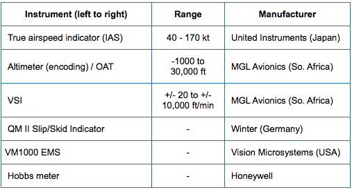
The instrumentation in N9103D is divided into three groups: flight and engine instruments, navigation and communications instruments, and electrical & support instruments. N9103D is not equipped for IFR flight. The components within each of these groups is described below.


• Vision Microsystems VM1000. This instrument provides:
Engine Tachometer
- Full-Sweep Analog Display
- Full Digital Readout
- Full-Color Range Marks
- Engine Hour Readout
- Flight Time Readout
- Max RPM Recorded for flight
Manifold Pressure (MAP)
- Full-Sweep Analog Display
- Full Digital Readout
- Full-Color Range Marks
- Overboost Alert for Turbocharger - Min/Max Recorded for Flight
Exhaust Gas Temp (EGT)
- ‘Diamond Graph’ on all EGTs
- Automatic Lean EGT Detection - Full Digital Readout
- Selectable Operation Modes
- Dual TIT Monitoring
- Full Color Range Marks
Fuel Pressure
- Full-Sweep Analog Display
- Full 2-Place Digital Readout
- Full-Color Range Marks
- Over/Under Pressure Alert
- Min/Max Recorded for Flight
Cylinder Head Temp
- ‘Diamond Graph’ on all CHTs - Automatic Hot CHT Detection - Full Digital Readout
- Selectable Operation Modes - Overtemp/Shock Cool Alert
- Full-Color Range Marks
- Min/Max Recorded for Flight
Fuel Computer
Full-Sweep Analog Display Full 3-Place Digital Readout Full-Color Range Marks
Low Fuel Remaining Alert Four Selectable Modes: Flow, Burn, Remaining, Add
Voltage
- Full-Sweep Analog Display - Full 3-place Digital Display - Full-Color Range Marks
- Over/Under Voltage Alert
Oil Pressure
- Full-Sweep Analog Display
- Full 2-place Digital Display - Full-Color Range Marks
- Over/Under Pressure Alert
- Min/Max Recorded for Flight
Amperage
- Full-Sweep Analog Display
- Full 2-place Digital Display - Full-Color Range Marks
- Low Amperage Output Alert - Min/Max Recorded for Flight
Oil Temperature
- Full-Sweep Analog Display
- Full 2-place Digital Display - Full-Color Range Marks
- Overtemp Alert
- Min/Max Recorded for Flight
• AirPath Magnetic Compass
• Fuel gauge assemblies, mechanical (2)
6.9.2 Navigation & Communications
The following navigation and communications instruments are installed in N9103D:
• Garmin/Apollo SL-15M Audio Panel
- Marker beacon receiver
• Garmin/Apollo SL-30 COMM/VOR
• Mid-Continent VOR/LOC & Glideslope Indicator MD200-306
• Garmin/Apollo SL-40 COMM
• Garmin/Apollo SL-70 transponder
• TCI R5-232 altitude encoder
• MGL Avionics encoding altimeter
6.9.3 Electrical & Support
The following electrical and support instruments are installed in N9103D:
• Electric trim with Safety-Trim elevator and aileron servo-speed controller
• Infinity Control Stick (pilot and co-pilot)
• Heated pitot
• PPAv XFR-J Fuel Pump Controller for auxillary tanks
• Facet 40105 fuel boost pump (left tank)
• Whelan anti-collision strobes and navigation lights
• Landing light (GE 100W, PAR 36, 4.5 inch diameter, beam width: 12° X 6°)
• Entertainment input (to SL-15M)
• ACK-450 ELT
- Remote and cockpit activation
• 12V auxiliary power jack (cigarette lighter socket)
• Instrument lighting
• Brow lighting (below glare shield)
• Buss status and charge indicator annunciator
• 12V battery jumper cable adapter in baggage compartment (Anderson Power Pole SB175)
6.9.3.1 Infinity Control Stick
Both the pilot and co-pilot positions have Infinity control grips. Each grip is equipped with six buttons to control various functions. Five of the buttons operate momentary contact switches and one operates a standard ON-OFF switch. The switch functions are as follows:
• "Coolie hat" switch: Operated with the thumb, this four-way switch controls elevator and aileron trim. Elevator trim is accomplished by pushing the coolie hat forward (for down elevator) and aft (for up elevator). Aileron trim is accomplished by pushing the coolie hat left or right in the desired trim direction.
• "Press-to-Talk": Operated with the forefinger, this switch activates that station's microphone circuit and places the selected communications radio in the transmit mode.
• "Ident": On the top of the grip and operated by the outside thumb, this green switch causes the transponder to “ident."
6.9.3.2 Elevator and Aileron Trim
N9103D is equipped with a TCW Technologies dual-axis Safety-Trim electronic speed controller with two speed presets. The elevator trim indicator is located near the radio stack. There is no aileron trim position indicator. The controller is designed specifically to operate the Ray-Allen T2 electric servo motors. A diagram of the elevator and aileron trim circuits is shown below. See also Trim-Servo Controller.
Safety-Trim provides the directional switching function as well as the adjustable speed control function needed to drive electric trim motors. Additionally, Safety-Trim provides a time limited operation (three seconds) of the trim servo motors that reduces the possibility of run-away trim conditions. Safety-Trim also has a reverse function switch that will allow recovery to a neutral trim condition even with a failed or inoperative trim switch.
The installation features two speed presets to allow Safety-Trim to operate the elevator and aileron trim servos at two separately adjustable speeds. These speeds are selected by use of an Omron flap-position switch located near the base of the flap handle. This is used to select a faster trim movement when the aircraft is at lower speeds (when the flaps are down), and a slower trim movement when the aircraft is at higher speeds (when the flaps are up).
The elevator and aileron servo speeds are independently set by adjusting the two potentiometers on the side of the enclosure, which is located below the pilot’s seat pan.
The servo speeds are marked Speed 1 and Speed 2. The range of adjustment is from about 5 volts to 12 volts. Turning the potentiometers clock-wise will increase the speed of the servo for each of the two respective preset speeds. The 2 speed switch connected to PIN #8 selects which of the potentiometers is used to control the servo speed. When the 2 speed switch is in the OPEN position, the potentiometer labeled SPEED 1 will set the servo speed. When the 2 speed switch is in the CLOSED position, the potentiometer labeled SPEED 2 will set the servo speed.

Safety-Trim schematic
Safety-Trim Operation
NORMAL Operation:
1) Place the power switch (which is located top-left-center of the instrument panel) in the “ON” position.
2) Use the trim input switches to drive the respective trim servo in the desired direction.
3) If you hold a trim switch closed for more than 3 seconds, the trim servo will stop moving the control surface. If you want more trim authority than commanded in 3 seconds, release the trim switch and press again. This will provide an additional 3 seconds of trim motion.
4) Any time you let go of a trim switch, the servo will stop moving.
REVERSE Operation:
If you have a trim input switch fail, either in a closed position or open position you may recover the airplane to a normal trim condition by moving the power switch from the ON position to the Reverse position.
The Reverse position is a momentary closure and you must hold the switch in this position to activate the reverse feature.
1) If you experience a failed trim switch in the shorted position your trim system will drive the servo affected for 3 seconds and then stop. To recover the aircraft trim system to a neutral trim condition, simply move the power switch from the ON position to the Reverse position. Hold the power switch in the Reverse position for as long as you need to recover the trim to a neutral setting. Then move the power switch to the OFF position and leave it there for the duration of the flight.
2) If you experience a failed trim switch in the open position your trim system will appear to be able drive the trim servo in only one direction.
To recover the aircraft trim system to a neutral trim condition, simply move the power switch from the ON position to the Reverse position. Hold the power switch in the Reverse position for as long as you need to recover the trim to a neutral setting. At the same time, press the trim input switch that is still functional. When the aircraft is properly trimmed, move the power switch to the OFF position and leave it there for the duration of the flight.
6.9.3.4 Cockpit Lighting
N9103b is equipped with two separate interior lighting systems. The "brow light" is an electroluminescent strip installed on the underside of the top lip of the instrument panel and extends the full width of the panel. The intensity of the brow light illumination is controlled by means of the lighting controller located in the upper portion of the left panel bay.
An instrument lighting system provides illumination for all of the instrument panel components. The instrument panel lighting is switched on and off by means of a rocker switch located in the Avionics/Electrical Switch Cluster. The intensity of the instrument lighting is controlled by means of a dimmer control located near the bottom of the right panel bay.
6.9.3.5 Engine Priming
Engine priming can be accomplished by pumping the throttle once or twice before starting (with the mixture control set to full rich). A momentary contact electric primer solenoid switch, located on the center console beneath the fuel selector valve, is inoperative.